The Do’s and Don’ts of BGA Reballing
Before touching the BGA, a technician must do extensive research and make important decisions. To determine whether they're using the right size solder ball, they should evaluate the BGA's solder ball size and check the coplanarity of the ball and the rest of the components. Following this check, the technician must make several important decisions, including choosing the right solder paste for the job, the correct stencil, and the right alloy and chemistry to ensure success.
After a technician has done his research and decided, a good technician will do the following:
- Examine the solder mask for damage
- Examine the PCB for damaged or missing pads
- Prepare the PCB and BGA by baking moisture out of the board and shielding heat-sensitive components to prevent damage or reflow.
Incorrect Equipment Selection or Inappropriate Material Selection
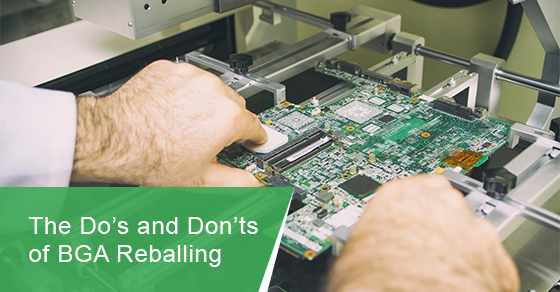
To perform BGA reballing, a technician's equipment needs to be flexible, capable of withstanding repeated use under controlled conditions.
To perform a job efficiently, technicians need to choose the best equipment for the job. You should look for equipment that offers a broad range of abilities and uses, from closed-loop thermal sensing and control, to applying heat or making precise markings.
To minimize BGA reballing issues in the future, do not take shortcuts when choosing your equipment. Solder joints voided by excessive solder are an example of common BGA reballing mistakes that can be avoided through proper material choices and equipment selection. Using the wrong solder paste for the material in question can void solder joints, which means residual solder must be removed from the BGA, and the process must be repeated if the voiding is more than 25 percent. Alternatively, the BGA may need to be rejected outright or reworked, especially if it compromises the solder attachment points.
Rework Issues Due to Inadequate Thermal Profiles
One of the most important things you can do is develop a thermal profile for each component if you are performing reballing or repair work on a BGA. Knowing what constitutes a proper profile and what does not can save you time and help you avoid rework and repair problems.
Because BGA reballing and repair is a repetitive process, it's difficult to put together a successful, repeatable rework process if you don't have good thermal profiles for your components.
Poor thermal profiles increase the risk of damage to the BGA, the PCB, and other components, which makes it take longer to fix the problem. Developing a good thermal profile involves ensuring that your thermocouples are properly positioned (especially when it comes to the PCB) and analyzing the data they provide. You need good, solid data to create an accurate, repeatable thermal profile.
Heat-Related Collateral Damage
Materials with improperly profiled thermal properties can lead to heat damage. Depending on which component was damaged and the severity of the injury, collateral heat damage can cause damage to nearby branches and lead to a host of other issues for BGAs.
If solder from adjacent components starts to reflow after it has set, you may end up with damage to the pads and leads, solder oxidation and starved joints, which can lead to a host of other problems that require time and effort to fix.
Professional technicians must know where to apply direct heat and how much to apply to different componets. Depending on the materials involved, a suitable temperature for one component could be disastrous for another. By developing a well-developed thermal profile for all of your components and controlling your process closely, you can limit heat migration when reworking the components, preventing future issues.
The Post-Placement Inspection Was Insufficient or Incorrect
There can be a lot of complexity in BGA components. Today's x-ray inspection machines make it easier for technicians to find and diagnose common BGA issues. An x-ray can now diagnose problems such as poor alignment, poor placement, or excessive voiding that once required hands-on disassembly for diagnosis.
For the x-ray machines to provide accurate data, the technician needs to understand what the machine is showing and then interpret the data provided by that image.
Post-placement inspections can reveal several problems, including a BGA that's incorrectly oriented. If you fix the orientation, you will have to rework more components and risk heat damage to the BGA and its surroundings.
In addition to BGA reballing and repair, there are also issues related to overall BGA design. BGAs with ultra-fine pitches (0.3 mm) are becoming more popular among manufacturers. In the BGA, angle refers to the distance between the centers of the balls. The driving force behind the desire for smaller and smaller components has led manufacturers to try and increase functionality within the same amount of real estate as the space between the two balls decreases.
Using the incorrect design specifications, however, can complicate matters. Because most BGAs on the market today are designed to be 0.5 mm or 0.4 mm, attempting to design a 0.3 mm BGA based on the same specifications can result in design mistakes, especially regarding the layout of vias and lands. On a PCB, "land" is what BGA device balls sit up against and ultimately get soldered to. An electrical circuit called a "fan-out" connects it to the "via," which distributes power and on/off signals from the device to the peripherals.
In addition to the design specifications themselves, the industry is already pushing its manufacturing capabilities to the limit with 0.5 and 0.4 mm BGAs. Tolerances have generally been in the +/- 3 mm range, but recent efforts to produce 0.3 mm BGAs have pushed them closer to +/- 1 mm. To validate and rework these new specifications, additional equipment is required. The use of 3D x-rays and advanced placement and rework stations will most certainly become standard in the future.
It is challenging enough to fabricate and assemble boards. It is imperative that PCB designers, reballing and repair technicians take care when working with fine-pitch BGAs. This includes considerations like the type of solder paste or underfill used, the type and thickness of stencil for placing the BGA balls, and other general equipment tolerances.
To learn more about BGA reballing service in Toronto, give us a call at 1 (888) 602-7264, fill out our contact form, or email us at info@circuits-central.com.