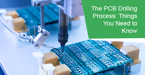
The PCB Drilling Process: Things You Need to Know
Printed circuit board (PCB) manufacturing in Canada is not easy. Circuit boards are full of holes, with some being needed in order to mount devices onto the board. The majority are used to interconnect the nets between the myriad layers of the printed circuit boards.
PCB manufacturing can be tedious at times because multiple holes will need to be drilled in order for the board to be fabricated. Due to the complexities involved in printing a circuit board, we feel compelled to provide an in-depth look into the PCB drilling process.
The Different Holes Involved
A raw circuit board will have many holes. The purpose of these holes will differ by quite an extent. For example, via holes consist of tiny openings that are plated with metal. Via holes are used to conduct ground, power, and electrical signals through the layers of the board. However, even via holes come in many different forms, including micro, blind, buried, and thru-hole.
Surface mount parts are frequently used for discrete and active components on many of the boards that are printed today. However, some may work more efficiently via a thru-hole package. The biggest benefit of a thru-hole package is that they provide robust mounting that is quite exceptional.
Certain mechanical parts, switches, and connectors will require a thru-hole package due to their delicate properties. Power components, such as voltage regulators, capacitors, monolithic resistors, and op-amps, may require a thru-hole package due to their heat and current conductivity.
Most of the circuit boards that are made today will have objects or mechanical features affixed to them, such as fans, connectors, and brackets. Holes will be required for mounting purposes. Mounting holes can sometimes also be used to disperse the components’ thermal heat to the inner layers of the plane.
The manufacturing process that is involved in board fabrication can be quite taxing, so mechanical holes may be required in order to facilitate the process. For instance, they may be used to properly align the board onto certain manufacturing equipment with automated properties.
Drilling Machines
Printing circuit boards may require a wide array of different styles and types of NC drilling machines. Certain large production variants can drill up to 35,000 holes per hour. These very same machines utilize optical guidance systems that are state-of-the-art and automated. Their precision is uncanny, and most are equipped with several air-bearing spindles. These leading-edge spindles can reach speeds that exceed 100,000 RPM.
The Drilling Process
The most common method of drilling a thru-hole hole in a board is to run it with its layers laminated via the machine. Soon thereafter, the holes will be plated on both the exterior and interior. The aforementioned process will be used for all thru-hole types, including mounting holes, components, and vias.
As for the sequential process of board fabrication, buried and blind vias are drilled before the board layer stackup is laminated.
Microvias are drilled with a top-of-the-line laser. Due to this process, they are much smaller than the holes that are made mechanically. It should also be noted that microvias can be connected together in a vertical manner. However, in order to do so, they need to be stacked together in layered pairs. Microvias are also usually made sequentially, similarly to standard buried vias.
Why Drill Selections Matter
In some cases, the board that you are working on may have a large number of drills on it that are of the same diameter. This may force you to change drill bits often while you are in the middle of drilling.
Tolerance errors may result, and they should be avoided whenever possible. Instead, you should change some of the drill sizes. By doing so, the number of drill holes for a particular size will be reduced.
Smaller drill sizes can cause many problems, especially if mechanical drilling is involved. The drill aspect ratio will be smaller, which will make plating arduous. The board may actually be forced into a laser drill process that is more expensive. Also, if you are working with boards that are thicker than 62 mils, then you will need to work with larger drill sizes.
In some cases, you may need to work with either buried or blind vias. However, if they are not a must for a high-density design or high-speed circuitry, then we would suggest that you not use them. The buildup process that is involved for buried and blind vias forces the boards that are fabricated to be more costly. If money is an issue, they should be avoided whenever possible.
Cost Analysis
As can be seen, there are several different aspects involved in drilling a PCB that can affect its accuracy or efficiency. The manufacturing costs will also be impacted by the many different aspects that we have discussed thus far.
For example, the size of the holes that are drilled will directly influence the cost involved. The cost will go up if the drilled holes are too small. Holes that are too big will also increase the assembly expenses, as they will complicate the process.
PCB manufacturing in Canada may vary depending on the company. Therefore, it is important to work with a company that has decades of experience and a proven track record of success.
The Circuits Central Difference
If you would like to learn more about PCB manufacturing, or would like to partner with a full-service PCB manufacturing company, then please visit Circuits Central at our website. We are experienced and dedicated connoisseurs in board assembly and electronics manufacturing. Over the decades, we have partnered with clients in the communications, commercial, medical, industrial, aerospace and defense, and power and renewable energy industries.
Our production services include rework, testing, printed circuit board assembly, and material management. We can also be reached at 1-888-602-7264 for a free, no obligation quote and consultation if you would like to discuss your PCB manufacturing requirements with our customer support team.

